
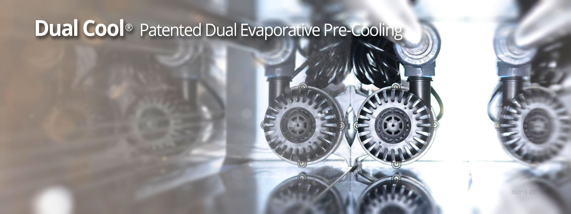
DualCool® was developed as a retrofit solution for commercial rooftop air conditioning units, with two basic goals: reducing peak electrical demand (kW) and reducing electrical energy use (kWh). Integrated Comfort Inc. has achieved both goals with our patented solution.
As the name implies, DualCool is providing cooling in two ways: direct evaporative condenser air pre-cooling and indirect cooling of the fresh air stream. Below you will find a detailed description of the components that make up the DualCool product.
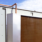
Pre-Cooler Enclosure
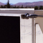
Pre-Cooler Enclosure
The major DualCool structural element is its stainless steel sheet metal enclosure that is custom-fit to each rooftop unit. This “unibody” assembly gains its strength from shape and connections rather than from metal thickness. The design facilitates an affordable “lifetime” enclosure that will outlast the rooftop unit to which it is attached. The integral bottom reservoir includes a screened stainless steel top that limits entry of debris, and the reservoir’s smooth flat bottom with rimless drain opening allows easy annual cleaning. On units with inward-slanting condenser coils, the enclosure includes hinged triangular panels that provide easy coil access. The unique design also facilitates easy removal of the evaporative media yet holds the media securely to prevent movement in windy conditions.
Submersible Pump
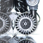
Submersible Pump
A submersible pump is the primary operating component in the DualCool system, moving cool water from the reservoir beneath the evaporative media to, and through, the vent air pre-cooling coil, and then back to a distribution tube above the evaporative media. Water flowing through the coil cools the warm incoming fresh air stream, and water flowing by gravity downward through the media cools the air entering the large condenser coil through which refrigerant is discharging heat to the outdoor air. The submersible pump strategy maximizes protection of this vital component, and maintains a clean unit appearance without external components and wires. ICI selected the current pump series for durability and energy efficiency after extensive lab and field testing. Pump access requires no tools; the technician simply pulls outward on the handle of the removable perforated metal media holder above the pump, removing the entire media section.
Evaporative Media
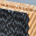
Evaporative Media
If the pump is the heart of the DualCool system, the evaporative media sections are the lungs. These 8” thick blocks of “cross-corrugated” treated cellulose are the highest quality evaporative media available, squeezing near-maximum cooling from the evaporative process. The heavy, dark “edge-coat” that ICI specifies for the media front edge provides protection against UV-degradation and damage from hardness minerals where groundwater is used. Both the airstream and the water are cooled evaporatively as water flows evenly downward from the stainless steel reflector above the perforated top distribution pipe. The condenser fans on the rooftop unit cause the air to flow across the media before passing across the condenser coil. Most media sections are 24” wide to streamline installation and removal. They are grooved at the top for retention against the wind, and are retained at the bottom in a perforated stainless steel tray. Media sections are easily removed for cleaning. The 3 to 7 year media life is mostly variable with hardness mineral content of the water.
Ventilation Air Coil
Ventilation Air Coil
This radiator-like heat exchanger cools the fresh air stream required by building codes to maintain indoor air quality in commercial buildings. It is also the feature that distinguishes the patented DualCool product from conventional condenser air pre-coolers. Cool water is pumped directly from the DualCool reservoir through this efficient coil, typically cooling outdoor air almost to indoor air temperature. The coil uses copper tubes and aluminum fins, and is carefully designed to drain water back to the reservoir when the pump turns off. Water leaving the coil flows to the distribution pipe atop the evaporative media, where it flows downward by gravity through the media to complete the water flow loop.
Standard Controls
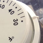
Standard Controls
The major DualCool control need is a thermostat that activates the pump when outdoor temperature exceeds a preset value (typically 70 to 75 degrees F). Earlier DualCool controls required low voltage power for pump and solenoid refill valve switching. (Since water evaporates to accomplish the cooling task, an automatic system is required to refill the DualCool reservoir.) The current basic DualCool control system relies on a line voltage thermostat and a simple, highly reliable float valve. This system takes advantage of the 115V service receptacle that is typically located in or on the rooftop unit. The DualCool thermostat is located inside the controls cabinet of the rooftop unit, with an external bulb temperature sensor. Like the pump, the float valve is easily accessed by removing a media block and its supporting perforated metal screen at one side of the pre-cooler.
Bleed System
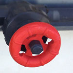
Bleed System
Where the supply water exceeds about 30 PPM of hardness mineral, ICI supplies a DualCool “bleed” system that limits the concentration of hardness minerals in the DualCool water loop. Without the bleed system, minerals can build up on all surfaces that the water contacts, compromising both appearance and function of the system. ICI technicians and trained DualCool installers measure hardness content of the supply water and specify a bleed rate. A bleed valve is then set to the specified rate. An upstream filter protects the bleed valve against clogging. Cleaning the bleed filter is important to maintaining performance and maximizing media life.
. . . . . . . . . . . . . . . . . . . . . . . . . . . . . . . . . . . . . . . . . . . . . . . . . . . . . . . . . . . . . . . . . . . . . . . . . . . . . . . . . . . . . . . . . . . . . . . . . . . . . . . . . . . .
SCHEMATIC COMPONENTS PERFORMANCE SUPPORT ECONOMICS